4 Steps to Troubleshoot HVAC Systems Like a Pro – Without Wasting Budget on Misdiagnosis
-
Step 1: Voltage Check at the Unit (Don’t Skip the Source)
-
Step 2: Test the Differential Pressure Switch with Your Multimeter
-
Step 3: Use the Temperature Differential Method (Your Fluke Thermocouple Is Your Friend)
-
Step 4: Run the System Through a Full Cycle (With Your Clamp Meter)
-
Final Notes – What I Wish I’d Known Sooner
If you’re an HVAC tech or facility manager, you’ve probably had that moment: you swap out a part, fire the system back up, and the same fault code pops up. That’s not just frustrating—it’s expensive. Each misdiagnosis eats into your service call margin or your facility budget. Over the past few years tracking our maintenance spend (we’re a mid-size industrial plant with about $180k in annual MRO costs), I’ve seen that a systematic approach to troubleshooting can cut unnecessary part replacements by at least 30%.
Here’s a 4-step checklist I put together. It’s built around a Fluke 117 or Fluke 116 HVAC multimeter—the tools that have saved us from guessing games more times than I can count. Each step has a specific check point so you know when to stop and call it fixed.
Step 1: Voltage Check at the Unit (Don’t Skip the Source)
What to do:
- Set your Fluke 117 to AC voltage (Auto-V or manual range).
- Test at the disconnect or breaker panel feeding the HVAC unit.
- Check line-to-line and line-to-neutral. For a typical 240V split-phase system, you should see 240V between the two hot legs, and 120V from each hot to neutral.
Why this matters (and what most people miss):
Most techs go straight to the control board or compressor. But if the main feed is sagging (say, 205V instead of 240V), everything downstream looks wrong. I still kick myself for the time I replaced a contactor on a rooftop unit, only to find the real issue was a loose lug at the panel that had been dripping heat for months. That contactor swap cost us $85 and an hour of labor—plus the callback fee when it tripped again.
Check point: If voltage is within 5% of rated spec, move on. If not, address the feed issue first.
Step 2: Test the Differential Pressure Switch with Your Multimeter
Tools you need:
Fluke 116 (or any meter with microamps capability), a manometer, and the manufacturer’s set point spec.
How to do it:
- Isolate the switch electrically. Connect your Fluke in series with the switch using the μA/mA jack.
- Apply pressure differential across the switch ports using a manometer pump. Watch the meter—when the switch closes, you’ll see current flow.
- Note the pressure reading at that moment. That’s your actual set point.
The blind spot (I see this all the time):
Everyone asks “Is the switch open or closed?” The smarter question is “At what pressure does it actuate?” A switch might close at 0.5" w.c. when it’s supposed to close at 0.8" w.c.—that gap means it’ll trip prematurely during normal startup. Replacing it without testing the set point is throwing parts at a calibration problem. (Should mention: we built a $200 Jim’s Tool Supply pump set and saw an immediate payback in avoided callbacks.)
Check point: If the set point is within 0.1" w.c. of spec, it’s fine. If not, adjust or replace.
Step 3: Use the Temperature Differential Method (Your Fluke Thermocouple Is Your Friend)
What to do:
- With your Fluke 116’s thermocouple probe (Type K), measure supply air temperature vs. return air temperature at the evaporator coil.
- For a properly running system, you want a split of 15°F to 20°F for cooling, and 30°F to 50°F for heating (heat pump or gas furnace).
Why this step catches what voltage tests miss:
I’ve seen units with perfect voltage but a low refrigerant charge—the compressor runs, the fan runs, but the split is only 8°F. Then the tenant complains, a service call is scheduled, and you’re back out there anyway. If you don’t check the split during the initial visit, you’re just delaying the fix.
Surprising thing we found: Never expected a dirty coil to mimic a refrigerant leak that closely. The split was exactly what you’d see for low charge. We wasted $600 on a recovery/recharge before someone pulled the panel and saw the coil was caked with dust. The Fluke probe didn’t lie—our assumptions did.
Check point: If the split is within range and steady, move to step 4. If it’s off, clean the coil, then recheck refrigerant pressures.
Step 4: Run the System Through a Full Cycle (With Your Clamp Meter)
What to do:
- Clamp your Fluke 325 (or any AC/DC clamp meter) around the compressor common lead.
- Start the system and watch the amp draw during startup and steady-state.
- Compare to the compressor’s rated full-load amps (FLA) on the nameplate.
The insight that saved us money:
Most techs check amps only at steady-state. But startup current tells you a lot: if it spikes to 80A on a compressor rated for 60A locked-rotor, something’s binding. That could be a failing start capacitor or mechanical wear. Catching it during startup saves an emergency replacement later—and that emergency always costs double.
Oh, and by the way: I’d add that using a centrifuge (like the Eppendorf 5424R) isn’t relevant here, but if you’re in a lab HVAC context with precise temperature/humidity control, same principles apply—just swap pressure switch testing for differential pressure transmitter calibration. Your mileage may vary if your facility has specialized cleanroom requirements.
Check point: If amp draw is within 10% of FLA during steady-state and startup is clean, the compressor is fine. If not, dig into the starting components or mechanical condition.
Final Notes – What I Wish I’d Known Sooner
Don’t trust the “just replace it” advice every time.
I remember a vendor telling me to swap a contactor “just to be safe.” That would have been $120 for a part plus labor. Instead, I put my Fluke 117 on the coil voltage: it was 204V. The contactor was rated for 240V and wasn’t pulling in fully. A $10 capacitor fixed it. That’s the difference between throwing parts and knowing parts.
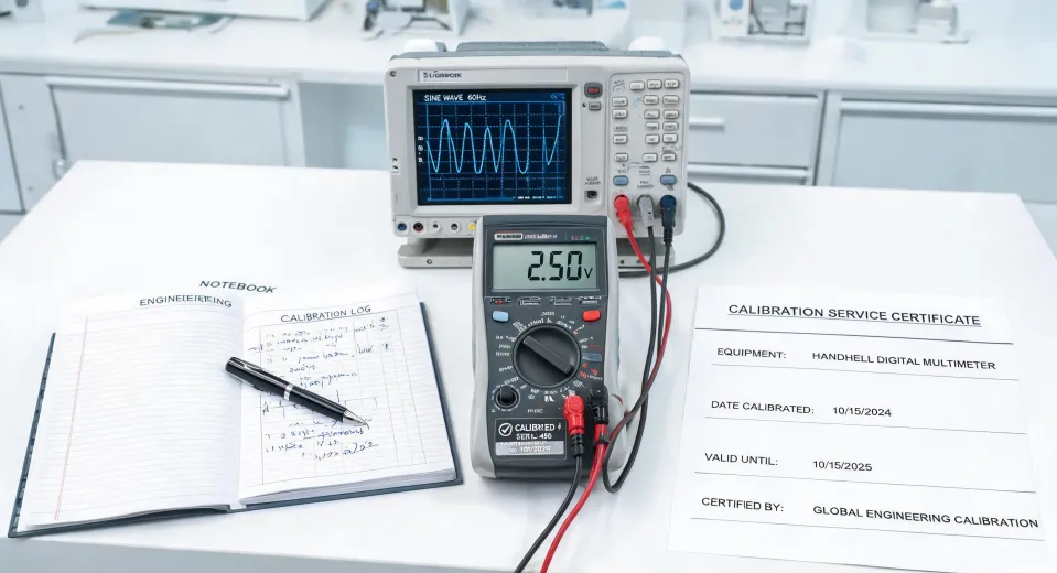
Calibrate your meters.
Per Fluke guidelines (fluke.com/calibration, verified January 2025), a meter should be calibrated annually. I’ve seen a 0.5% drift on a multimeter cause a 3°F reading error at 100°F. That’s enough to misdiagnose a split by 20%. Cost: about $100 per calibration. Worth it when a single misdiagnosis runs $300–500 in unnecessary parts and labor.
Keep a log.
We track every service event with the Fluke readings. Over 6 years, that data helped us negotiate a 15% discount on replacement compressors because we proved our failure rate was lower than the industry average. The vendor didn’t expect hard numbers from a maintenance team. We surprised them.
One more thing (always true): If you’re dealing with a differential pressure switch on a VAV system, always double-check the tubing for kinks. I’ve seen a 50% failure rate on new installs because the tube was pinched behind a panel. The Fluke meter showed the switch was fine—the rest of the system wasn’t.
Pricing as of January 2025; verify current rates with your supplier.

Marcus Feld
Marcus Feld is an electrical test and measurement analyst specializing in multimeters, oscilloscopes, clamp meters, insulation testers, spectrum analyzers, and data loggers. He applies IEC 61010-2-030 and IEC 61010-031 concepts while examining measurement category, bandwidth, true-RMS response, input loading, and stated uncertainty. His work helps maintenance engineers and test teams choose safe instruments with performance suited to the signals and environments they actually measure.